

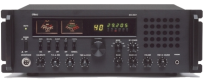
This 50 Ohm load can easily dissipate 30 Watts and operate up to 1 GHZ!
Resistance alone can not dissipate such power, it will fix on a large radiator.
We often find in flea markets amateur radio.
When this resistance dissipates the power supplied by the transmitter a voltage appears at its terminals.
Just measure it and deduce the power,
it is the role of the components connected in parallel on the resistor.
When this resistance dissipates the power supplied by the transmitter a voltage appears at its terminals.
Just measure it and deduce the power,
it is the role of the components connected in parallel on the resistor.
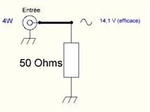
For a power of 4 Watts RF,
we deduce with Joule's law that the effective voltage across R is:
U = Root of P x R (Root of 4x50 = 14,1V (eff.))
This is an RF voltage at the transmitter frequency.
It is therefore necessary to detect this sinusoidal voltage to make it continuous
and be able to measure it with a simple Voltmeter.
Just measure it and deduce the power,
it is the role of the components connected in parallel on the resistor.
For a power of 4 Watts RF,
we deduce with Joule's law that the effective voltage across R is:
U = Root of P x R (Root of 4x50 = 14,1V (eff.))
This is an RF voltage at the transmitter frequency.
It is therefore necessary to detect this sinusoidal voltage to make it continuous
and be able to measure it with a simple Voltmeter.
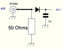

The detection circuit is composed of a diode and a capacitor.
The diode passes the positive half-cycle and blocks the negative half-cycle,
the capacitor charges at the peak value of the positive half cycle.
The value of the DC voltage is 14.1 x root of 2 = 20 volts.
The diode passes the positive half-cycle and blocks the negative half-cycle,
the capacitor charges at the peak value of the positive half cycle.
The value of the DC voltage is 14.1 x root of 2 = 20 volts.
On the diagram "next page" there are 2 diodes!
Indeed, if one wants to measure a power of 30W, one has 55V at the terminals of the diode!
The 1N5711 is a low-threshold Schottky diode (~ 0.3V)
that rises very high in frequency but can not withstand a reverse voltage greater than about 60 volts.
To avoid working near its limit value I put two in series.
The actual value across the capacitor will be: 20 - 0.6 = 19.4V.
The galvanometer is used to measure this voltage,
so it must as any voltmeter be as sensitive as possible so as not to disturb the measurement.
I used a 100μA recovery model.