
Adjustment of the load :
If it is impossible to find in standardized values of resistances,
the appropriate value to obtain a load of 50Ohm,
it is still possible to be at 51 Ohm for example and decrease this value
using resistance of different value.
51 Ohm in parallel with 3300 Ohm (3.3k Ohm) will form an equivalent resistance of 50.22 Ohm.
The ROS thus obtained will be very low and very close to 1: 1.0044
Note for the construction:
It will be necessary to ensure:
- use non-wound resistors (classic carbon layers will do)
in order not to introduce a reactive component (inductive in this case)
and distort the final impedance of the load.
- Make connections between short resistors:
each end of tracks behaves (according to the frequency) like an inductance.
- To dissipate the heat produced by the load.
5Watt is a huge power for a ¼ Watt resistor
and it may misbehave or even break, which could damage your transmitter.
Shielding:
The load may have track lengths that may slightly radiate.
In this case we will use a metal case (connected to the ground) to shield our load.

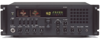
I propose: the realization of a power meter with load 50 Ohms - 30 Watts
Characteristics :
- Impedance 50 Ohms.
- Two scales of measurement, from 0 to 10 Watts and from 0 to 30 Watts.
- Frequency 1 to max. 500 MHZ.
Operation:
The power of the transmitter reaches a resistance of 50 Ohms
which behaves like a fictional antenna because it does not radiate.
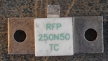
The resistance must be non-inductive and be able to dissipate the power of the transmitter.
It can be made even by grouping trade resistances
but if you want to go high in frequency it is better
to use a real non inductive resistor like this one below.
Characteristics :
- Impedance 50 Ohms.
- Two scales of measurement, from 0 to 10 Watts and from 0 to 30 Watts.
- Frequency 1 to max. 500 MHZ.
Operation:
The power of the transmitter reaches a resistance of 50 Ohms
which behaves like a fictional antenna because it does not radiate.
The resistance must be non-inductive and be able to dissipate the power of the transmitter.
It can be made even by grouping trade resistances
but if you want to go high in frequency it is better
to use a real non inductive resistor like this one below.
250N50 = 50 Ohm 250 Watt